Chapter 2
Reference plant for waste incineration with CO2 capture

Chapter 2
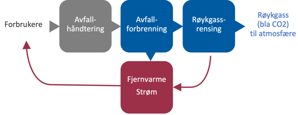
In order to assess which CO2 capture technologies are suitable for waste incineration, a reference plant "KAN Referansa" has been established to reflect the waste incineration plants in the KAN group. In a simplified way, the figure below shows the main cycle for waste, energy and flue gas (which contains the CO2). A typical waste incineration plant has a district heating network connected to and produces electricity with a steam turbine. The flue gas is cleaned to satisfy emission requirements and then discharged to the atmosphere. Both waste incineration (in blue) and district heating/electricity (in red) are considered.
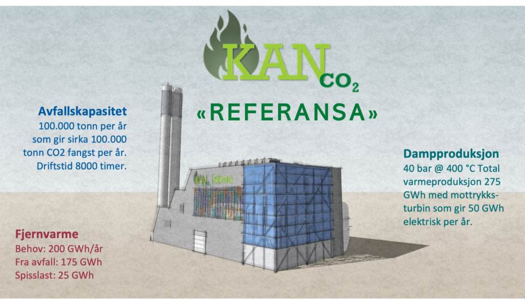
"KAN Referansa" has a capacity of 100,000 tons of waste per year and operates 8,000 hours per year. With a goal of capturing 90% CO2, the amount of CO2 that must be sent to storage is thus also 100,000 tons per year.
The waste incineration produces steam at 40 barg and 400 °C with a total heat production of 275 GWh, which with a typical back pressure trip bin gives 50 GWh in electricity production per year, of which 10 GWh is used internally for combustion. After touring, most of the heat (175 GWh) is used in a district heating network that has an annual need of 200 GWh and must therefore have a peak load of 25 GWh. The rest of the heat must be cooled during the summer when the demand in district heating networks is low.
2 The waste incineration cycle with CO2 capture
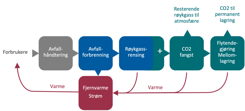

Blue represents the existing plant (waste incineration with flue gas purification) without carbon capture and storage.

Red represents district heating/steam with electricity production.

Green represents the capture plant, where the sub-process with a small plus symbol is "pre-action" can include both parts of existing flue gas cleaning and new treatment steps necessary to capture CO2 in the flue gas from waste incineration and temporarily store this liquid at local CO2 storage.

The arrows from the plants to district heating represent auxiliary systems/integrations/etc. and deal with measures at the interfaces between waste incineration, district heating, capture plants, other energy supply, etc. Transport of captured CO2 is described in more detail in the chapter Transport and intermediate storage.
2.1 Types of energy production
Waste incineration plants can recover heat from the incineration of waste in various ways. This is shown in the table below. In most cases, the heat is recovered into heat for the district heating network and/or electric for electricity production. Some plants with multiple combustion lines may have a combination of the different alternatives in the table. Hot water systems will provide somewhat larger district heating deliveries.
| Plant design | Energy production | Implications for carbon capture |
|---|---|---|
| Hot water circuit | No electricity production and only district heating | Steam is not available for carbon capture and if the technology requires this, the steam must be made separately. |
| Steam with back pressure turbine and cooling directly against district heating | 15-20% of the energy is converted to electricity and 85-80% to district heating, available for turbine bypassing. Excess district heating is cooled away. | Steam can be used and can be obtained in four ways: - Steam is taken upstream turbine, this is relatively simple but reduces electricity production. - If the turbine is adapted, the steam can be taken from an intermediate step in the turbine, which gives the best efficiency and slightly less loss in power production. - Steam is taken upstream of the turbine and expanded through a new counter-pressure turbine adapted to the needs of the trapping leg. - Steam is run through the existing turbine and repressed with a steam fan. |
| Steam with two stage turbine | 15-25% of available energy is converted to electricity in two-stage turbine, drainage to district heating at the intermediate stage, vacuum condensing with cooling. |
2.2 District heating, reference
The waste incineration plants are connected to locale district heating systems of different sizes and different seasonal variations. The proportion of delivered power and energy of district heating that comes from the waste plant will vary from place to place and over time. Ownership and control of district heating also varies from location to location. At the same time, the link between waste incineration and local district heating represents a key factor for smart integrations when introducing a carbon capture plant. Temperature conditions for district heating round trip and return also play a role in the possibilities for integrations.
Based on known duration curves for various remote district heating plan, a reference district heating network has been established. Key figures for this district heating network are as follows:
- Demand in the district heating network: 200 GWh (75 MW peak)
- Available waste heat: 175 GWh (88% of delivered heat in district heating)
- Peak load from alternative source: 25 GWh (12% of delivered heat in district heating)
- Hours of waste heat at maximum power: up to 3000 hours per year.
from January to December.
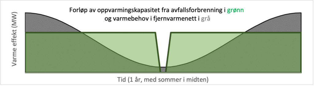
Duration diagram for "KAN Referansa" without carbon capture plants
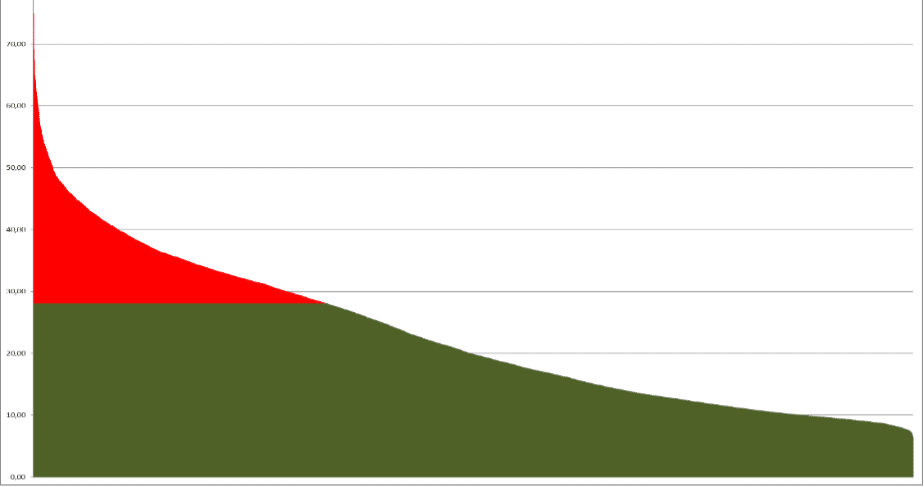
Power efficiency against district heating
In contrast to pure power plants and pure industrial processes, Norwegian waste incineration plants are largely base load in district heating plants where the "load" has large seasonal variations. The waste fuel lines therefore have longer periods of "excess heat" that can fully or partially cover the energy needs of a carbon capture plant.
Today's largest incineration plant in Norway varies greatly in how long the plant has full power utilization against district heating networks. This time can vary from 5% of the year to over 40% of the year and the lower this figure, the higher the potential for CO2 capture to utilize this heat. The higher the number, the more power a capture plant will have to take heat that was previously used in district heating networks.
Energy utilization
The largest waste incineration plants in Norway vary between 65% and 95% total energy utilization. The higher the number, the more of the heat that is cooled away because it cannot be used in the district heating network.
Plants with low energy utilization will have several hours where delivery of heat to a CO2 capture plant will not adversely affect district heating deliveries. Increased need for extra peak load or need for small integrations will be lower for plants with low energy utilization.
2.3 Combustion technologies
The two most common combustion technologies in pre-combustion plants are grate combustion and combustion with CFB (Circulating fluidized bed).
The main difference between these is environmental performance and emissions. CFB typically has lower NOx and SOx emissions compared to grate combustion, which among other things makes it easier to meet the requirements for flue gas composition for a CO2 capture plant.
In Norway, grate combustion is most widespread and there are two additions that use other technology. Haraldrud uses CFB, while Averøy uses gasification.
The reference plant is based on grate combustion.
2.4 Flue gas cleaning, reference for smoke gas cleaning
Configuration flue gas cleaning and flue gas composition
Despite the fact that waste incineration has the same emission requirements to adhere to, flue gas can vary considerably from plant to plant. The location and age of the facility affect these conditions. Chimney flue gas temperature varies from 60 °C to 140 °C and flue gas composition may also vary significantly, even if they are below limit values.
Why is this important?
It is important to do a thorough mapping of the flue gas composition under different operating conditions. Different components of the flue gas can affect the grading rate of amine solvents and adding guidance for material selection in the capture plant to prevent corrosion. There may also be a need to make upgrades or introduce new cleaning steps in the flue gas cleaning system to meet the requirements for smoke-gas composition from a capture plant. If these factors are not considered in the design, there will be a risk of increased operational/maintenance costs and downtime at the plant.
One can assume that it will be both necessary and sufficient to upgrade existing facilities to Best Available Technology (BAT) requirements for 2023.
In the reference process, all flue gas must be cooled from 120 °C to a maximum of 55 °C.
The reference for flue gas cleaning is defined as follows: "The flue gas purification plant has a configuration and necessary treatment steps so that only cooling and preconditioning (SOx) of flue gas in a DCC prior to absorption is required. DCC and a new flue gas fan to overcome pressure drops on the gas side are included in the delivery to the supplier of the capture plant."
2.5 The carbon capture plant
Standard description of the capture facility
MEA (30wt%) amine plant is the type of CO2 capture plant that is used as a reference plant for CO2 capture. This includes covering outlets near existing chimneys until expired by coolers downstream of CO2 strippers. The plant is dimensioned to capture 90% of CO2 in the flue gas with an annual capacity of 100,000 tons of CO2.
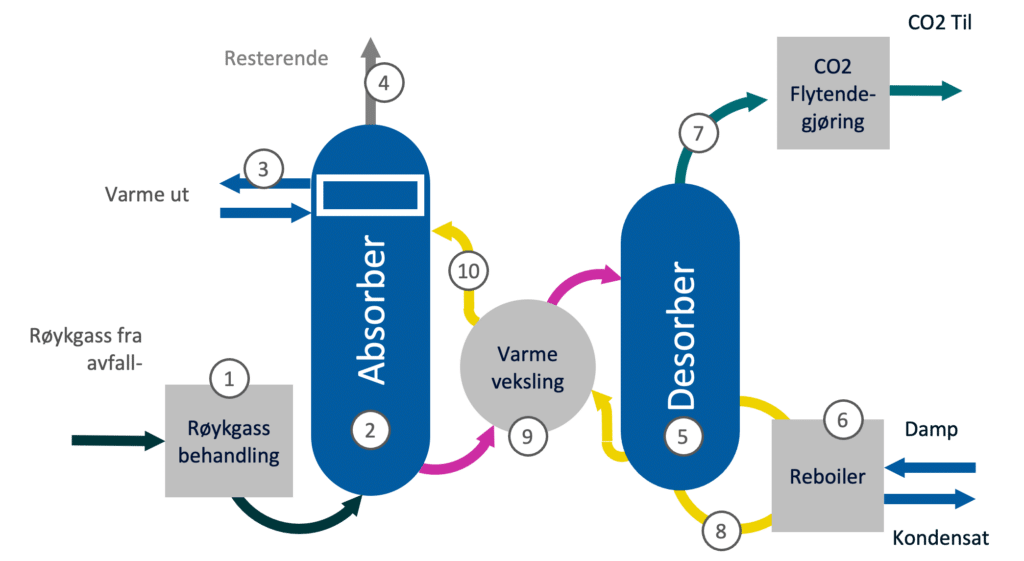
(1) Direct contact cooler (DCC)
Before the flue gas is introduced onto the absorber in the catch deposit, it passes through a direct contact cooler (DCC). The purpose of the DCC is divided in two:
(a) cool the gas to a temperature level where absorption of CO2 is most efficient (typically around 40-55 °C for amine)
(b) Wash away corrosive components such as SO2, etc. by adding lye.
The flue gas is cooled below its original dew point and there will also be condensation of water in DCC. This water flow must be transported to a separate water purification plant for treatment and disposal of waste products. The flue gas leaving the DCC will be at the dew point. Downstream ducts and fan must be in corrosion-resistant materials.
(2) Absorber
In the absorber, CO2 in the flue gas is bound to the solvent solution through a chemical reaction. For amine solvents, the reaction gives off heat so that a temperature gradient is obtained above the absorber. Since the absorbency of amine is best at low temperatures, efficiency decreases as the temper rises through the absorber. Typically, the temperature of flue gas/amine is 60 °C when it enters the washing step (6) on top of the absorber.
A large contact surface between gas and solvent is crucial to ensure efficient absorption. To increase the contact surface, one section of the column volume is filled with packing material. The packing will be a resistor that generates more pressure drop. This must be compensated for by dimensioning the flue gas fan upstream of the capture plant. Solvent without CO2 is added to the upper part of the absorber, while solvent saturated with CO2 is pumped out from the bottom.
(3) Absorber water wash section
When temperatures rise, water and amine will evaporate. To prevent amine emissions above permissible limits, and reduce water loss from the capture plant, one or two water wash sections are installed in the upper part of the absorber. The water washer cools and condense evaporated water/amine. In addition, a drop catcher is installed, which effectively captures small droplets.
(4) Absorb stack or return to existing chimney
After the water wash, purified flue gas exits the absorber. Depending on local conditions and emission requirements, flue gas must be reheated to ensure sufficient dispersion in the event of a discharge. In many cases, after heating must be done using a heat source in the waste incineration plant. The flue gas can also be fed back to the chimney for waste incineration. Assessing this must be done per situation/location.
(5) Desorber/stripper
After the CO2 is absorbed, solvent with CO2 is pumped to the desorber/stripper column. The solvent is added in the upper part of the column. In the desorber, the solvent is heated to typically 120 °C (for amine) and CO2 is driven out of the solvent. In the same way as in the absorber, a large contact surface between the gas phase and the liquid phase is necessary to ensure efficient stripping of CO2. A section of the column volume is therefore filled with packing material to increase the contact area. The desorber is pressurized (typically 1 barg) and the pressure helps to compensate for pressure drop over the pack- king section. CO2 and water vapor leave the top of the desorber.
(6) Reboiler
Heat to boil out CO2 from the solvent solution is supplied in a reboiler. The solvent solution is supplied in a boiling liquid bath on shell-side and the boiling process is driven by CO2 and water vapor. Typically, saturated low-pressure steam (vapor pressure approx. 2 barg) is used on the pipe side of the reboiler, but hot water and hot oil can also be used.
Typical specific heat demand for this MEA process with standard process configuration is 3.6 MJ/kg CO2, which corresponds to 1 MWh/ton CO2 caught.
(7) Overhead stripper condenser
CO2 and water vapor exit on top of the desorber and maintain a temperature of typically 110 °C. The gas is cooled to approx. 30 °C before it goes to the installation for compression, conditioning, drying and liquefaction. When cooling in the overhead strip per condenser, a large proportion of the water vapor will condense. Water and CO2 in the gas phase are separated in a condensate tank, where CO2 gas saturated with water steam goes to the CO2 compressors, and condensed water is pumped back to the desorber.
(8) Reclaimer
Over time, most solvents will degrade because of contact with impurities in the flue gas. To remove the degradation products, a reclaiming process is normally included. Regeneration is done as needed and the frequency will depend on the amount and type of impurities that are in the flue gas.
The degradation rate depends on the type of solvent and many of the proprietary amines developed by technology vendors are claimed to have very low degradation rates.
(9) Cross heat exchanger
Since absorbers and desorbs have different drift temperatures, a cross-heat exchanger is inserted where hot solvent without CO2 (typically 120 °C) is heat exchanged for cold solvent with CO2 (typically 50-60 °C). In this way, energy is saved for cooling and heating solvent in absorber and desorber respectively.
(10) Lean amine cooler
After the cross-heat exchanger, the solvent without CO2 still has a slightly high temperature, therefore the solvent is further cooled in a separate heat exchanger before it enters the absorber.
CO2 compression and liquefaction
After OH Stripper Condenser (7), stripped CO2 is led to a compression and liquefaction plant. Compression is energy-intensive and requires cooling utilities.
Given the reference plant, the thermal energy requirement of the stripper at full operation is estimated to be 12.5 MW and 100 GWh per year.
2.6 Capture as a service
Some of the suppliers offer different variants of capture as a service. Indications have been given that the cost of such services may be down to NOK 1100-1300/tons CO2. Of this, costs amount to between NOK 400-600 per ton. What will be included in such a service is unclear, but it will probably require that the service provider receives a prepared site, and access to the necessary heating, cooling, and other auxiliary systems necessary for operation of the facility.
In Norsk Energi's opinion, a project operated as "capture as a service" will have to be planned and executed as if it had been carried out without such an "operational service". If the supplier is to deliver the capture service, including its own energy supply, there is a great risk that more costly solutions will be chosen, since the possibility of smart integrations will be more inaccessible.
Given that the service provider must take increased risk by bidding capture as a service, one must expect that there is also a risk premium in the price.
2.7 Investment cost (Capex)
Establishing a benchmark for investment cost (capex) for a retrofitted carbon capture facility is challenging. A capex estimate will be afflicted with different uncertainties at different maturity levels.
The capex of the project will be largely governed by the client's quality requirements. A site-built specially adapted capture plant with plenty of space for access and its own process building will have a higher capex than a standardized modular solution based on containers and prefabricated solutions. On the other hand, a customized plant can be more cost-effective when the plant is large (several hundred thousand tons of CO2 per year).
Design requirements and functional requirements in the project's design basis are therefore expected to have a major impact on the final capex of the project. The actual CO2 capture facility is also expected to account for only a small proportion of total capex, where factors such as land purchases, buildings and ground, cooling water facilities, compression, liquefaction, and intermediate storage are also included as significant cost factors.
A synthesis report from the Swedish Energiforsk (Eliasson et al. (2021)) proposes the following simplified formula for calculating the investment cost of a CO2 capture plant, including compression. It is thought that this formula does not include local construction tanks, land costs and groundworks.
[1000 EURO] = 15520 x ton per hour CO2^ 0.6339
[1000 EURO] = 15520 x 12,5^ 0,6339 = 77 MEUR
For the reference plant, this formula gives a total expected capex of 77 MEUR assumed without ground work.
One of KAN's partners, BIR, has through feasibility studies and other preparatory work estimated that a plant with a capacity to capture 100,000 tons per year from waste incineration in Bergen must have an investment budget of approx. NOK 1 billion. This confirms that the formula gives a good initial estimate, given that the formula is only for the capture plant itself without project-specific costs.