Chapter 2
CO2 capture technologies

Chapter 2
Which capture technology is best suited for the waste industry and for cost-effective CO2 capture?
In order to answer this question, we need first an overall look at methods and technologies. This will include methods that cannot be directly used by existing waste incineration plants, but which may nevertheless be in "competition" in a market for CO2 emissions. The simplest example of carbon capture is planting or protecting forests, and although this method may be considered uninteresting in the context of waste incineration, it must be considered what is the most sensible choice.
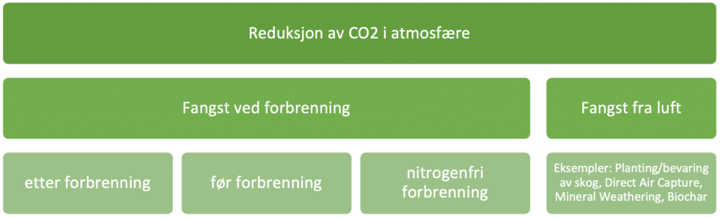
Of course, reducing CO2 emissions is not the same as actually taking CO2 out of the atmosphere, but the methods have some overlap. Waste incineration lies in this overlap, due to the fact that the materials have both fossil and biogenic origins. Reduction of CO2 in the atmosphere can be done either by capturing where biogenic material is burned or by taking it directly from the air.
The are many known methods that take CO2 from the air and there is a lot of activity around research on technologies and so-called "geoengineering". To avoid going too deep into the topic (geoengineering), only simple examples are mentioned; planting trees, direct air capture, mineral weathering and biochar. Such methods have an enormously wide range of advantages and disadvantages that are difficult to map, and the effects are also difficult to measure. In addition, most methods are assumed to be less efficient than capture by combustion, due to the low concentration of CO2 in the atmosphere compared to the concentration of CO2 in flue gas. In order to achieve the temperature rise targets (1.5 °C according to the Paris Agreement), the international community will probably have to use "every tool in the drawer" that can reduce CO2 in the atmosphere. For example, technology that captures CO2 directly from air (DAC) will not exclude the need for CO2 capture from waste incineration. Still, it may be necessary to set priorities, especially when it comes to making investments. In this case, overall assessments show that capture from waste incineration is a very efficient way of capturing CO2, primarily because of the high concentration of CO2 in the flue gas (10%) and because there is often a lot of energy available, especially in the summer months.
On the other hand, the current market for CO2 emissions trading will try to find the most cost-effective tool, at least if waste incineration is to be allowed to sell its "negative emissions" in this market. In this sense, the different ways and technologies of CO2 capture will actually compete against each other. This type of assessment is not included in this delivery L2 which compares technologies. These issues require continued global political cooperation and the handbook will go a little deeper into this in "Delivery 6 Financing and Business Opportunities".
For all CO2 capture technologies, there are some genetic challenges that recur:
- Energy demand (heating/power/cooling)
- Size (footprint/volume)
- Costs (capex/opex)
- Environmental considerations and verification of these (emissions to air/water emissions/noise)
These challenges are also competitive advantages between the technologies according to how well the challenges are solved. As technologies mature, these issues are expected to be handled better and better, and consequently the presentation below is considered a picture of status today. There is considerable development on several of the technologies presented below, so this picture is expected to change over time.
Post combustion capture
At an overall level, there are four fundamentally different technologies for carbon capture after combustion; absorption, adsorption, membranes, and cryogenic distillation, as shown in the illustration below:
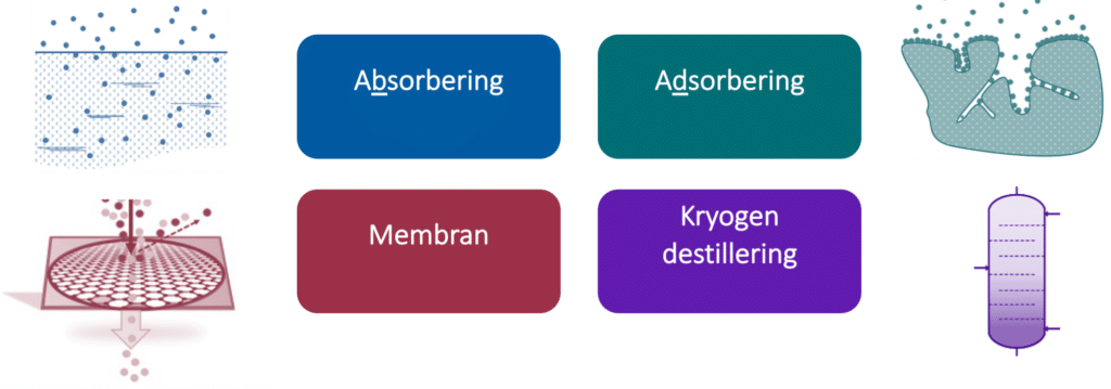
Absorption is done with a capture medium (usually liquid) that absorbs CO2. The absorption can be either chemical (reactive) as salt formation in amine, or non-reactive (physical) as solubility of CO2 in water. After the capture medium is saturated with CO2 in the absorption part of the process, the equilibrium is changed by changing temperature or pressure to remove CO2 from the capture medium in the desorption process. This process is repeated by circulation of the trapping medium between the two main parts of the process.
Adsorbing has a substance (most often solid) that adsorbes CO2 in contact with the flue gas. This means that CO2 adheres to the surface of the substance. Afterwards, CO2 is released from the substance again. This is done with pressure or temperature. Typically, solids circulate in powder form, or the flue gas is sent through tanks with solids that are then subjected to pressure/temperature fluctuations to release CO2.
Membrane technology passes the flue gas through a membrane that only lets most CO2 through. Based on the permeability and partial pressure of CO2 in the flue gas, CO2 is let through in a 50:1 ratio typically. The flue gas is pressurized to a higher pressure and passed through several membranes to achieve proper cleanliness. One can struggle to get a high enough CO2 concentration with this technology without having too many steps.
Cryogenic distillation cools the flue gas to under the dew point of CO2 (-79 °C) to condense out CO2. The refrigeration is based on the Joule-Thomson effect and is used extensively to produce pure oxygen or nitrogen. A relatively high CO2 concentration is required to be able to use this technology. One advantage is that you get liquid CO2 as a product and not in a gaseous state.
Within each of these technologies, there are again several different variants. In addition, one can combine several of the technologies. A favorable combination is that both membrane technology and pressure-driven adsorbing are combined with cryogenic distillationbecause the latter requires high CO2 concentrations and produces liquid CO2 (which is often desirable) while both technologies struggle to deliver high CO2 concentrations. In some cases, absorption is also combined with membranes for increased purity of CO2 for use in the food industry.
Absorption
Absorption is the most widespread technology for carbon capture, there are several solvents and capture media. A representative selection of these is presented here.
Amines
TRL 9 (there are variants with expected benefits and lower TRL).
Capture using amines is the most widespread and can be considered the most mature of the capture technologies.
There are many varieties of amines and mixtures of these, but the chemically simplest of them, Mono Ethanol Amine (MEA), is often used as a base case against which different technologies measure themselves. The amine is dissolved in water and is called solvent.
A detailed description of the process can be seen in Chapter 3.5.1. In short, the solvent is circulated between two columns, while the flue gas is cooled in direct contact with water to around 40°C before it is introduced into the process. In the first column, solvent and flue gas meet upstream in direct contact and CO2 is absorbed into the solvent in the Absorber. The solvent, which is now rich in CO2, is then pumped into the second column through a cross exchanger and in the other column the CO2 is boiled off. This column is called a Desorber or Stripper. The CO2 that has been boiled off is sent on to compression and liquefaction, while the solvent that is now poor in CO2 is sent back to Absorb through the same heat exchanger ready for a new round of capture. This heat exchanger is called a cross exchanger and can be recognized in most CO2 capture plants with liquid solvents. This saves the process a lot of energy needs.
Large amounts of energy are needed to boil off CO2, and there are many different measures that are used to limit this energy demand. This is also one of the main challenges with amine technology. Other amine mixtures with lower energy requirements, more cross exchangers, compressors in the process, insulation, exchange of heat between capture and compression are some of the measures used.
Other challenges with the amine process are emissions to air of amine compounds, degradation of solvent and the need for its regeneration, corrosion of pipes and tanks and consequently the need for more expensive equipment, large footprint, and large volume due to high columns and generally large costs in both capital and operations.
All these challenges have been addressed by many suppliers and research institutions over a long period of time, and there is still a lot of work to be done on further improvement. Technology has come a long way, much has been solved, but there is still much left. And since it is difficult to circumvent physical laws that dictate high energy consumption, etc., other technologies have been developed with advantageous aspects compared to amine processes.
Suppliers
Air Liquide - Aker Carbon Capture - Baker Hughes – Compact Carbon Capture - Cansolv (Kanfa, Carbon Centric) - Honeywell - Fluor - Mitsubishi Heavy Industries (Drax) – et al.
Advantages
High maturity
Many suppliers
Low project risk
Disadvantages
High heat demand
Chilled ammonia
TRL 7
Capture with ammonia is not unlike the amine process, but also has an extra absorber and an extra desorber to avoid ammonia release. On the other hand, it requires more cooling of flue gas to temperatures down to 2-10 °C and operates at a higher temperature and pressure in desorber. The process has high power consumption compared to amine processes, but lower heat consumption. Chemical consumption is significantly higher than for amine, but no separate reclaimer is needed to remove the degradation product. One challenge that must be addressed with this process is deposits of solids. Ammonia is also an affordable industrial chemical. It produces ammonium sulfate as a by-product of the process. Ammonia is toxic and flammable as a gas and will have strict handling requirements. Unlike amines, there will be no release of substances that could potentially lead to cancer. The process is described as being robust to contaminants in the flue gas, including acidic gases such as SO2 and NOx (Ola Augustsson, 2017). In KEA's 2016 assessment of Aker Clean Carbon's amine process (now Aker Carbon Capture) and Alstom's CAP process (now Baker Hughes), the processes were equivalent. The results from testing at TCM were considered successful, after initial problems, according to statements from key personnel in Gassnova/TCM.
Suppliers
Baker Hughes
Advantages
High maturity
Lower energy consumption than amine
Affordable capture medium
Disadvantages
Higher power consumption than amine
Few suppliers
High consumption of capture medium
Toxic and flammable capture medium
Potassium carbonate pressure
TRL 7
Potassium carbonate is an inorganic material that has high solubility in water. Upon absorption, CO2 binds to potassium carbonate and water, forming potassium bicarbonate (2KHCO3). When heated, the bicarbonate will decompose into potassium carbonate, CO2 and H2O again. Potassium carbonate has a limited rate of absorption of CO2 from the flue gas. Therefore, there is a need to have additives. This is what distinguishes the different suppliers in that different substances are added as well as differences in the desired pressure in the absorption column.
HPC is considered TRL 6-7 on flue gas after combustion by the authors due to lack of testing.
Due to the pressurization of the flue gas, there are also greater demands here for dust reduction than with amine, for example, which can use a more robust fan solution. Pressurization of flue gas also has an HSE perspective to be assessed.
Suppliers
CO2 Capsol
Advantages
Gode muligheter for å levere høy temperatur varme til fjernvarme.
Disadvantages
Medium maturity
Potassium Carbonate Enzyme (carbonic anhydrase)
TRL7
Saipem CO2-Solutions uses a proprietary enzyme-based solution in their process. The enzyme, also called carbonic anhydrase, is also found in living organisms, and catalyzes the transition between the different forms of inorganic carbon: carbon dioxide (CO2), hydrogen carbonate (HCO3, bicarbonate) and carbonic acid (H2CO3). The enzyme is very efficient (up to 106 reactions per second) and has an important function in photosynthesis and respiration, as well as it participates in acid-base equilibrium and pH regulation in cells. https://www.mn.uio.no/ibv/tjenester/kunnskap/plantefys/leksikon/k/karbon-anhydrase.html
CO2 solutions has a commercial plant in Canada (Resolute, Saint-Fèlicien (Quebec) – pulp mill), which captures approximately 20 tons of CO2/day during stable operation and is designed to 30t CO2/day. Thermal energy use in the form of hot water is stated to be 2.4 GJth/ton CO2 and has no negative effect on the upstream processing plant. The heat is also stated to have zero value. The cost of electrical energy is stated at 7.35 CAD $/ton CO2 (CO2-Soluti- Wed, 2019), which at a value of CAD $ 0.06/kWh (average consumer Quebec) gives electrical energy consumption of 0.44GJel/ton CO2. Thermal energy consumption of 2.4 GJ/h CO2 and electrical energy consumption of 0.5 GJ/t CO2 are in the order of magnitude equivalent to what can be expected of modern amine solutions. Bearing in mind that this enzyme-based solution should require a lower temperature (40-70 °C) at partial vacuum. At Klemetsrud, the technology was tested at 85 °C.
Suppliers
Saipem CO2 Solutions
Advantages
Low temperature favorable for integration with district heating
Disadvantages
Low Maturity
Kilde: www.mn.uio.no
Calcium Looping Process
TRL 6
Calcium Looping Process (CLP) captures CO2 with a circulating limestone-based sorbent that is subjected to cyclic carbonization-calcination reactions. CaO is exposed to the flue gas at approx. 600 °C.
This process uses two fluidized bed reactors in which the following reversible reaction takes place:
CaO + CO2 <-> CaCO3
The first reaction is called carbonization and is exothermic (ΔH=−178kJ/mol), where CO2 is captured on the sorbent and the solid is transported to the second reactor. An endothermic calcination (ΔH=+178kJ/mol) occurs in the second reactor which emits a clean stream of CO2 which is compressed and sent to storage. The two fluidized bed reactors are interconnected for the facilitation of transport of solids. Cyclone separators are used to separate solid and gaseous mass flows.
Source: www.sciencedirect.com
“Process integration of Calcium Looping with industrial plants for monetizing CO2 into value-added products”
Adsorption
Pressure Swing Adsorption
TRL 5
Pressure Swing Adsorption (PSA) is based on the phenomenon that gases under high pressure tend to adsorb on solids surfaces. The flue gas is pressurized and passes through a tank filled with the adsorbent, CO2 adheres to the adsorbent, and when saturated, the smoke gas supply is shut off and the pressure is lowered, releasing CO2. The pressures are typically up to 6 bar (g) and only use electricity (not heat).
PSA works at low CO2 concentrations, but produces difficult purities above 60-70% CO2, PSA only uses electricity (not heat). PSA+cryogenic is a combination that can give promising results.
PSA is at a research stage, which means it is far from a finished product.
Suppliers
No known commercial vendors
Advantages
No known harmful emissions
Disadvantages
Low Maturity
Process with solids can be challenging
Temperature Swing Adsorption
TRL 4-5 Oppdatert til 7 (8. januar 2025)
Temperature Swing Adsorption (TSA) baserer seg på fenomenet at adsorbenter tenderer til å adsorbere mer ved lavere temperaturer. Røykgassen er typisk sendt gjennom en CO2 adsorbent ved lavere temperaturer. Når adsorbenten er mettet stenges røykgasstilførselen av, temperaturen heves, noe som frigir store deler av CO2-gassen. Deretter kjøles adsorbenten ned igjen til en relativ lav temperatur og gjenbrukes i prosessen. For gjenvinning av ca. 90% av CO2, bør adsorbenten varmes til ca. 250 100-110°C (oppdatert 14. januar 2025). Adsorbenten kan adsorbere CO2 ved omgivelsestemperaturer på ca. 30 °C.
Suppliers
Svante
Advantages
No known harmful emissions
Disadvantages
Low Maturity
Process with solids can be challenging
Cryogenic distillation
TRL 7
Cryogenic distillation is, as the name indicates, a distillation process at low temperatures. By cooling the flue gas to around -50 °C, CO2 condenses into liquid. Other volatile gas compounds such as nitrogen and oxygen remain gas at these temperatures, and CO2 can thus be relatively easily removed as a liquid. The product from this capture process is thus liquid CO2, so liquefaction is included in the capture process. It is also possible to lower the temperature further and extract CO2 as solids, also known as dry ice, but this is thought to rarely be profitable on energy use and cost.
Cryogenic distillation is not suitable for low CO2 concentrations. The higher the concentration of CO2, the more suitable this method is for capture. The process is therefore poorly suited for capture from a gas turbine (3-5% CO2) and better for capture from the cement industry (20% CO2), while waste incineration is somewhere in between. The process is also well suited in combination with membranes or PSA, often as the last step after membrane step with 1:50 or approx. 80% CO2. In this way, one can manage with a step membrane and end up with fully liquefied CO2 of high purity.
Cooling can be done with conventional cooling circuits that are usually powered by electricity in the compression of the refrigerant. In other words, there is a significant need for electricity, but no need for steam or heat.
Suppliers
Air liquide
Advantages
No need for steam/heat
Available waste heat
Disadvantages
Low Maturity
High power consumption
Membranes
TRL 7
Membrane technologies for carbon capture plants are often polyethylene oxide based, for plants of this type it often consists of several steps. Each membrane must have a driving pressure difference over it. This technology does not require heat, only a power requirement. It can be challenging to achieve the right CO2 concentration in a membrane plant. This may be a good idea to investigate for capture plants that do not have steam or hot water available, but access to cheap electricity. Returkraft in Kristiansand is testing a pilot with this technology.
Membranes separate CO2 from flue gas through a dense membrane film layer. The flux of CO2 in the membrane is the sum of the permeability and solubility of CO2 in the membrane film, which is typically based on polyethylene oxide. The membranes do not 100% excrete other components of the flue gas, but the separation is typically 1:50. In other words, 1 part nitrogen and 50 parts CO2. To achieve a sufficient concentration of CO2, typically 2 steps of membrane are used to reach a purity of over 95%. Alternatively, it can be used in combination with other technologies such as cryogenic distillation.
The driving force for pushing CO2 through the membrane is pressure difference and is preferably carried out at relatively modest pressures and temperatures. Typically, some 100 mBar plus minus atmospheric and 30-50°C.
Compared with absorption with amines, the maturity of membrane technology is low. That said, there is great progress and some larger pilots have already been tested with promising results. There is a lot of demand from the market, and the technology does not differ very much from other industrial applications such as reversible osmosis filters - ring of seawater to fresh water. The main challenge seems to be the lack of large-scale production of the membrane film itself, which in turn could reduce costs.
Suppliers
Air Products – Air Liquide – Honeywell – Membrane Technology Reserarch – Compact Membrane Systems – Cool Planet Technologies – Aqualung Carbon Capture – OOYOO Ltd. – CoorsTek Membrane
Advantages
Low energy consumption
No need for steam/heat
Area efficient (and volume efficient as there is no need for high absorption/desorption towers)
Disadvantages
Low Maturity
High power consumption
Pre combustion capture
Pre combustion capture is largely about changing the combustion process to achieve a cleaner flue gas that mostly contains only CO2. The following sub-chapters provide an explanation of some capture technologies before combustion.
Pre combustion capture by gasification
Gasification allows CO2 to be removed from fuel before combustion is complete. It is a well-known technology in coal-fired power plants, but for incineration of residual waste it is not widely used. However, there is an increasing number of players looking at this type of technology, especially in the context of the production of synthetic fuels such as methanol.
In gasification processes, a feedstock is partially oxidized in steam and oxygen/air under high temperature and pressure to form synthesis gas. This synthesis gas is a mixture of hydrogen, CO, CO2 and smaller amounts of other gaseous components, such as methane. The syngas can then undergo the water-gas shift reaction to convert CO and water (H2O) into H2 and CO2, producing an H2- and CO2-rich gas mixture. The concentration of CO2 in this mixture can vary from 15-50%. CO2 can then be captured and separated, transported to final storage while the H2-rich fuel is pre-burned into water (H2O).
The synthesis gas is rich in CO2 and at high pressures, allowing easier removal before H2 is combusted. Due to the more concentrated CO2, capture before combustion is usually more efficient, but the capital costs of the baseline gasification process are often higher.
Suppliers
HTW – High Temperature Winkler technology – GIDARA Energy (gidara-energy.com)
Nitrogen-free combustion (Oxyfuel combustion) In nitrogen-free combustion, oxygen is separated from nitrogen in a separation unit so that digestion can be done with pure oxygen. The result of this is that you get out CO2 and water after combustion, which can go straight to further processing and storage.
There are some challenges with this.
- Combustion with pure oxygen results in very high temperature which makes it difficult to build combustion chambers in conventional feed rials. This is mitigated by circulating the combustion air and thus limiting the temperature.
2. It requires significant energy to separate oxygen from nitrogen.
3. It is ill-suited for retrofit as the pre-burning chamber itself needs to be modified.
Chemical Looping Combustion
Chemical looping combustion (CLC) is very similar to nitrogen-free combustion and is a collective term for processes where oxygen from combustion air is added to combustion in a reactor using oxygen carriers. These oxygen carriers are often metal oxides. In this way, the Nitro gene is excreted in the air before combustion and CO2 and water are left after combustion. This process also takes place with circulation between two re-actors. In one, the oxygen carriers capture oxygen from the air, and in the other, the oxygen is used up in the combustion/oxidation process together with the fuel.
Until now, this process has had challenges with metal oxygen carriers getting stuck to different parts of the processing equipment. Once these practical challenges are resolved, it seems like a promising process with lower energy consumption than conventional nitrogen-free combustion.
Alternative capture methods worth mentioning
The capture methods presented here are not directly relevant for installation at a waste incineration plant. However, they represent an important reference in this benchmark study.
Direct Air Capture
Direct Air Capture (DAC) is a collective term for all technologies used to capture CO2 directly from the air. In other words, it is a partly technology-neutral concept, but there are clear common features. Capturing CO2 from the air is more energy-intensive and therefore costly than capturing it from a point source. This is because CO2 in the atmosphere is much more diluted than, for example, in the flue gas from a power plant or a cement plant. This contributes to the higher energy demand and costs of DAC compared to other CO2 capture technologies and applications.
Direct Air Capture – Analysis – IEA.
Planting forests
Not directly relevant for point emissions, but a very effective method for CO2 capture over time and thus relevant for a benchmark study.
Total storage in above-ground vegetation, underground vegetation and in the soil has been determined on average during the first 100 years to be 2.4 tons of carbon per year per hectare. The first years are more effective than the last. Compared to the total cost of industrial capture, compression and storage, the cost is low. However, the cost has great variation, so it is difficult to pinpoint with one figure, but seems to be somewhere between USD 5-100 per ton of CO2. Source: www.nature.com