Chapter 3
Cooling of unused waste heat

Chapter 3
The capture plant has a continuous cooling requirement of 20.2 MW, regardless of the seasons. For "KAN Referansa" it is essential that the heat can be cooled away when it cannot be delivered to the DH network. That is, a cooling system must be installed that can cool 20.2 MW on a 'hot' day. When the DH requirement is present in winter, heat pumps will cover much of the cooling from the capture plant.
If it is essential to cut the maximum power requirement for cooling, the solution with a HP supplying steam to the capture plant can be profitable, which will cut the maximum cooling power from the capture plant to 14.7 MW. This will require more cooling of heat from the waste incineration plant, but it is reasonable to assume that the infrastructure for this already exists.
If it is possible to take the heat from the capture plant (2.6 MW from OH condenser and CO2 compression and liquefaction) directly to the DH grid on the return, this should be used. As shown in Figure 2, the DH grid always has a heat requirement of at least approx. 6.5 MW. This will mean that the capture plant will only need an installed cooling capacity of 17.6 MW. In GWh over the year, it will increase the cooling of the turbine heat, but there is already installed cooling capacity for this.
8.1 Local Cooling - Dry Cooling/Cooling Tower
The reference plant has assumed that all waste heat will be cooled through dry coolers on the roof. Dry coolers are at the mercy of the outside temperature, it is assumed that the Dimensioning Outdoor Temperature (DOT) is not warmer than 25 °C, and on days when it is possibly warmer than 25 °C it can be accepted that the cooling water back to the capture plant will be somewhat warmer than 25 °C. Some capture technologies will have the ability to vary the round-trip temperature of cooling water according to season. It is about 110 hours per year with outdoor temperatures warmer than 25 °C. Subchapters 8.5, 8.6 and 8.7 cover possibilities for cooling down to 25 °C cooling water when the outside temperature is 25 °C or higher.
For simple calculations of electricity consumption, it is assumed that the average outdoor temperature when cooling is needed is 15 °C, and that the air is heated to close to 25 °C. Furthermore, a power consumption of 0.09 W/(m3/hr) of air is assumed. When calculating area requirements, it is assumed that there is 2 °C between the outside temperature and the cooling water temperature, in addition to 50 % relative humidity.
Dry coolers have a significant area requirement, figures from suppliers show that the area requirement is approx. 0.032 m2/kW cooling power (assuming 2 °C between outside temperature and cooling water temperature). The need for space becomes even greater if there are restrictions on sound levels.
A total area requirement of approx. 640 m2 for the carbon capture plant if the heat from OH condenser and CO2 compression and liquefaction cannot be used directly for the DH return is required.
The area requirement will be approximately 560 m2if the heat from OH condenser and CO2 compression and liquefaction can be used directly for the DH return.
If the waste heat is used through a HP for steam production for the capture plant, the area requirement will be 425 m2, as part of the cooling requirement is covered by HP.
If you use the waste heat through a HP for steam production to the capture plant and extract the high-temperature heat OH condenser and CO2 compression directly to the DH return, the area requirement is 340 m2, as the cooling is covered by the DH return and steam producing HP.
A typical dry cooler block in a V layout is shown in Figure 62.
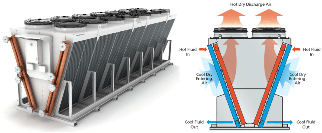
This is not included in the area requirement for cooling for the heat from the turbines in the summer, as it is reasonable to assume that a cooling effect has already been installed for this. For some waste incineration plants, this can cause noise level challenges, which should be carefully considered. Requirements for lower sound levels typically result in lower fan speeds and the need for larger heat exchange areas. Relevant suppliers are ABK-Qviller, Kelvion, Thermo Control, Eptec, Aircoil, Reftec, etc.
8.2 Increased inlet temperature of absorber
It is normal to assume/specify an inlet temperature for flue gas to absorber of approx. 40 °C, this depends on the capture supplier. The temperature specification implies a significant cooling requirement for incoming flue gas in the capture plant's direct contact cooler.
Studies carried out by a player in the KAN network (Stat-kraft) together with TCM show that although higher inlet temperature (up to 55 °C) results in slightly increased heat demand in stripper (reboiler duty), the reduced cooling requirement and effect on heat integration is so significant that higher inlet temperature should be considered. For this study, as previously mentioned in subchapters 6.3 and 7.2, an inlet temperature of 55 °C has been assumed. It is perhaps somewhat more realistic that this one is lower.
8.3 Use of the district heating system as a cooling source
Normally, the return temperature in a district heating system is so high (55-70 °C) that it can contribute little or no cooling of a CO2 capture plant without the use of heat pump technologies (see Chapter 7).
If the return temperature in district heating is sufficiently low, it can be used to cool the capture plant partially or completely by direct heat exchange, without the use of heat pumps. This would be highly energy efficient and cost effective.
Two of the players in the KAN network have therefore investigated whether it is possible to use the district heating system itself to a greater extent as a cooling source with a greatly reduced return temperature. In the two studies, it was investigated whether it was possible to reduce the return temperature of district heating by heat exchange of the return flow towards a low-temperature heat load (e.g. seawater cooling) elsewhere in the district heating system. Such cooling of DH return enables a significantly higher proportion of direct heat exchange without the need for heat pumps. The solution would also utilize existing infrastructure in a very efficient way since existing pipeline networks can be used. Such a scheme is feasible, but the management of such a system was considered slow and difficult to control. The two companies chose not to further develop the concept of artificial cooling of DH return.
Actions to reduce the return temperature from DH customers will always be positive and improve the capacity and efficiency of the district heating system.
If the supply of cooling to the capture plant is limited (for example by very high air temperatures on a hot summer day or little surplus area), one or more of the heat pumps (described in Chapter 7) may be a solution to ensure the final cooling of the plant by compulsory upgrading of energy to the DH network. Such forced upgrading of the waste heat will cause the extra added heat to be;
- dumped in the district heating dump coolers in the waste incineration plant,
- accumulated in the district heating system,
- dumped at another location in the DH network, e.g. a heat user/cooling source (seawater cooling at a different location).
The possibility of such forced operation of the heat pumps as described above may contribute to less stringent design requirements being imposed on the capture plant's cooling system, for example by allowing the design temperature for dry cooling fans on the hottest day to be higher than 25°C. Such operation with compulsory use of heat pumps is clearly less efficient than pure cooling solutions, but since it is probably only a few hours per year of operation, the solution with less installed cooling capacity (reduced Capex) and short-term "forced operation of the heat pumps" can still provide good cost-benefit.
8.4 Seawater cooling/district cooling
Waste incineration plants with immediate access to the sea or other natural refrigeration sources can advantageously use this as a cooling source for the carbon capture plant during periods when there is no need for waste heat towards district heating or internally in the capture plant.
One of the KAN operators has indirect access to seawater cooling through a district cooling network established close to the capture plant. The district cooling network, built to provide comfort cooling, has a temperature design of 9/16°C. By increasing the temperature difference in the district cooling network from 9/16°C to 9/37°C, it was possible to quadruple the district cooling network's capacity to supply cooling in the same pipe network. The district cooling center itself needs to be upgraded with a more heated surface, and new assessments of the discharge point had to be carried out since the energy supply to the sea was significantly changed from the original design. The study showed that the district cooling network could essentially maintain initial capacity for delivering comfort cooling while ensuring a cost-effective cooling solution for the carbon capture plant.
This integration is a special case that is only relevant where local conditions are right.
8.5 Absorption cooling
Absorption cooling is based on the same principles as in absorbent heat pumps, shown in section 7.1.2. Absorption cooling uses a salt, often lithium bromide (non-toxic and low GWP) to cool colder than the environment, requiring only external heat instead of electricity. DH can be used to power the absorption cooling. This is relevant if it is important for the capture plant to cool the cooling water colder than the outside temperature, especially during the summer months. It is important to mention that absorption cooling also has waste heat, but at higher temperatures, a system sketch of an absorption cooler is shown in Figure 63, here chilled water at 6°C is supplied.
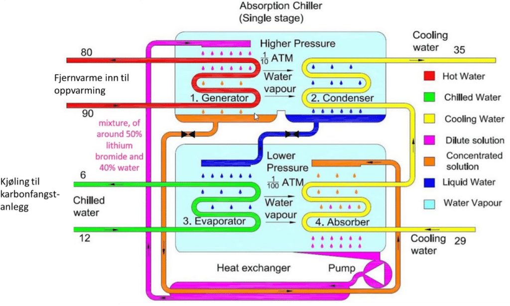
Absorption chillers define COP as usable cooling capacity divided by the thermal energy entered. With DH input of 90°C, one can typically expect a COP of 0.7, i.e. if you need 7 MW of cooling, you must consume 10 MW of DH.
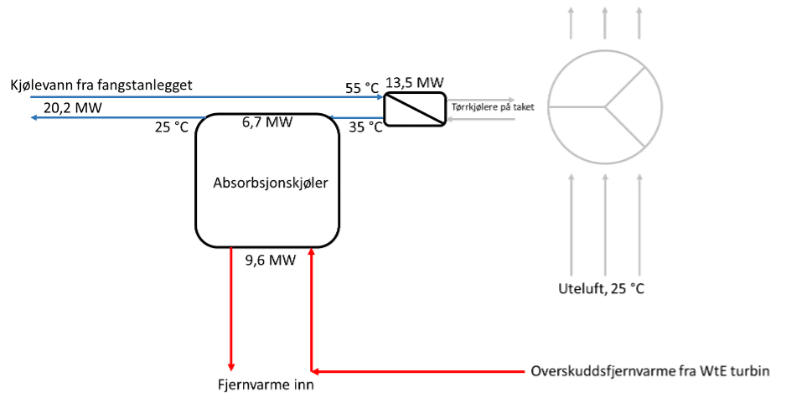
If there is a need on the part of the catch supplier for cooling from eg. 55 down to 25 °C, this will be fine with air from outside when the outside temperature is colder than 25 ° C, then the DH requirement is often high. The need to cool to colder than the atmospheric air will mainly be in the summer months, then you also have a surplus of DH from WtE, because the DH demand is low. In other words, absorption cooling is a good way to ensure sufficiently low temperatures during the summer months using DH excess from WtE. At an outdoor temperature of 25 °C, you can cool from 55 °C down to 35 °C with outside air in dry coolers, and from 35 °C down to 25 °C with absorption cooling. This is shown in Figure 64.
Relevant suppliers of these are the same as for absorption heat pumps, shown in section 7.1.2.
8.6 Sorptive cooling
Sorptive cooling utilizes external heat at high temperatures to cool. Air changes its temperature if the moisture content changes, and the enthalpy is constant. The principle is that the outside air is first dried with district heating in a sorption rotor, and then humidified with water that evaporates, increasing humidity and lowering the temperature. The sketch is shown in Figure 65.
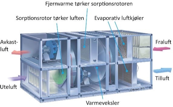
This is done, for example, for office buildings in Mo Industrial Park, where there is access from a relatively large proportion of district heating from the nearby industries. It is not widespread to any great extent in society, and it is largely intended for air cooling. Like absorption cooling, it will fit well with the DH profile when the outside temperature is above 25°C because the process consumes heat to provide cooling. The advantage sorptive cooling has over absorption cooling is that the temperatures needed are somewhat lower than the DH temperature. For example, you use the DH return and cool it down further. Relevant suppliers are Munters AB.
8.7 Evaporative cooling
Evaporative cooling sprays water on the air into the chillers. The water is often colder than the surrounding water and a higher moisture content in the air provides better heat transfer and lower temperature of the air. This is a way of cooling the air before the air again cools the waste heat from the capture plant. This has a water consumption, which is significant, which makes it comparable to cooling with available mains water.
This will provide adequate cooling on days when the outside temperature is too high.