Chapter 3
Heat supply to capture plants
Chapter 3
The capture plant has a large need for heat, in accordance with the heat available in the incineration plant. If the existing plant does not have heat available either as steam or as hot water, it is assumed that the heat can be supplied from an electric boiler as a basis.
6.1 Integration with existing steam plants
Most providers of CO2 capture technology require low-pressure steam for the stripping process. It is normally appropriate for this steam to be collected from the steam plant for waste incineration, where possible.
In general, the steam of the carbon capture plant should be obtained at the lowest possible pressure, e.g. by draining from the steam turbine at the operating pressure needed at the carbon capture plant, in order to maximize power production. However, this is not always possible or practicable. For an existing plant, a modification of the steam turbine to enable steam extraction at the lowest possible pressure is unlikely to be cost-effective. For a plant with a multistage steam turbine, draining steam from one of the intermediate stages will be an advantage.
For plants with multiple combustion lines and combinations of turbine configurations, it will be appropriate to connect to the steam system at several locations. This provides flexibility for optimization when heat demand varies. For example, some waste incineration plants are equipped with both a counter-pressure steam turbine and a condensing steam turbine. In such cases, it may in some cases be appropriate to prioritizes steam for the condensing steam turbine to maximize power production. This typically occurs in summer when the heat demand of the capture plant and district heating system is lower than the capacity of the waste incineration plant. Similarly, a back pressure turbine with direct condensation against remote walls will achieve better overall energy utilization since all energy is retained in the energy systems and as little as possible cooled away in vacuum condensers.
Integration with existing steam plants
For "KAN Referansa", it is assumed that steam for the capture plant is obtained upstream of the steam turbine. As a result, the electrical power produced and available heat for district heating are thus reduced. Drained steam is cooled in a desuperheating station where feedwater is added to achieve the correct pressure and steam temperature according to the specification from the carbon capture plant.
The draining of steam (12.5 MW) reduces power generation (-2.25 MW) and district heating (10.25 MW). This corresponds to a loss of 180 kWhel/ton CO2 captured and 820 kWhDH/ton CO2 captured.
The adaptations to the existing steam system are shown in the figure below, the changes towards the carbon capture system are shown by the dotted line, the steam of the reboiler is taken upstream turbine, which reduces power generation and DH delivery.
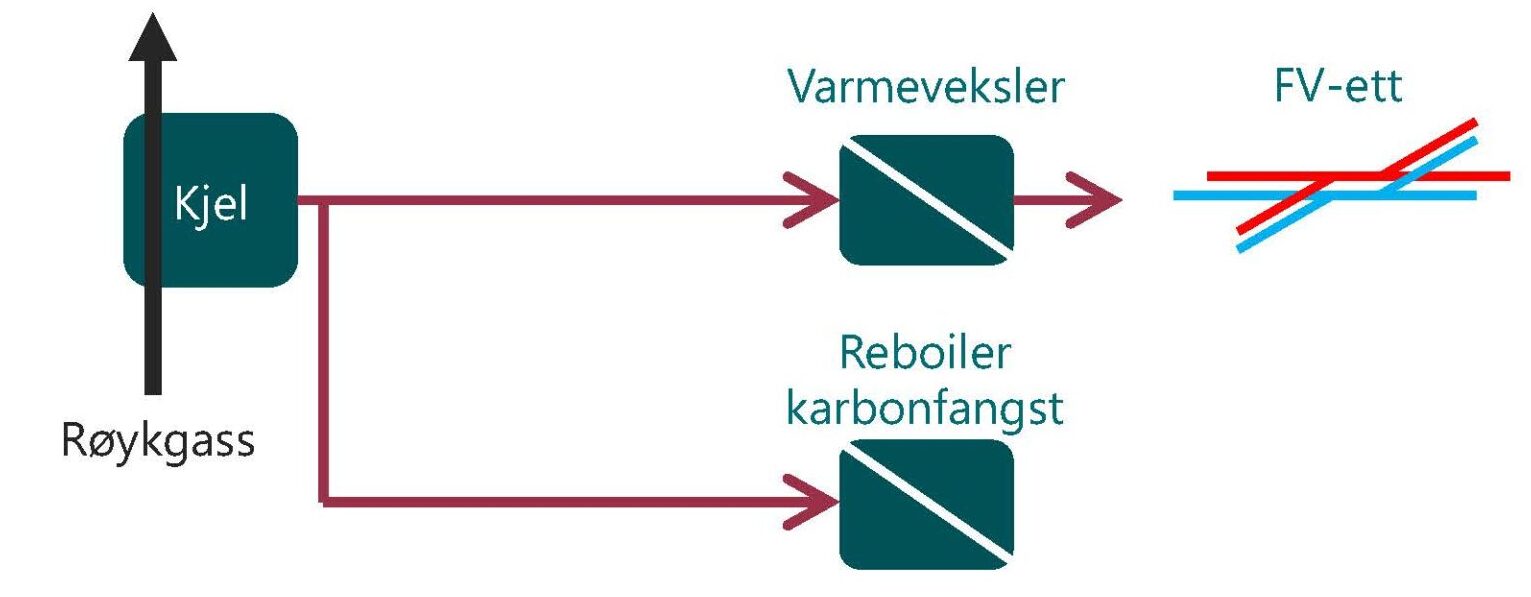
With the reduction of the DH delivery, it is important to maintain the same conditions for the steam out of the counter pressure turbine so that the condensation pressure is not greatly altered. Ideally, one then reduces the mass flow with DH water to maintain the same temperature difference on DH in the exchanger. This must be clarified with the turbine supplier.
It is important to check that the turbine can operate as normal with a reduced amount of steam throughout, usually steam turbines can be operated with a minimum of 1/3 of the maximum steam flow.
6.1.2 Turbine types and alternatives
Condensation turbine at vacuum pressure
The power generation lost will depend on the turbine type; if the plant has a draining condensation turbine that takes out vacuum vapor.
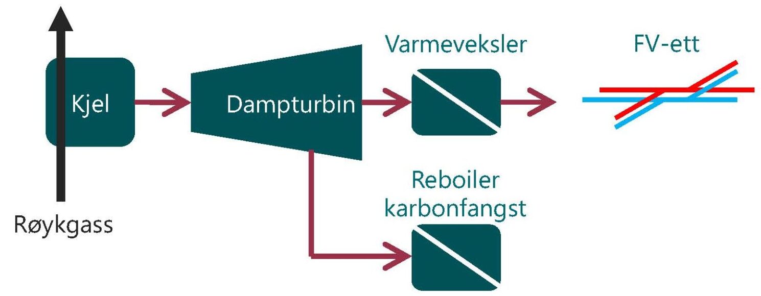
Draining on adapted pressure from existing turbine
In an ideal scenario, tapping from the existing turbine (counterpressure turbine or condensation turbine) at the correct pressure, as shown in Figure 15. This would have resulted in maximum power production. Modifications of existing turbines for new drains are expensive, but not necessarily technically feasible, as the turbine must have a minimum flow throughout.
In a new plant, a turbine system should be designed with the carbon capture plant in mind, with possibly more turbines.
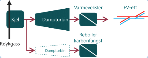
New counter-pressure turbine on bypass steam
An alternative is to install a new smaller counter pressure turbine that reduces pressure based on the amount of steam the capture plant needs, as shown in Figure 16.
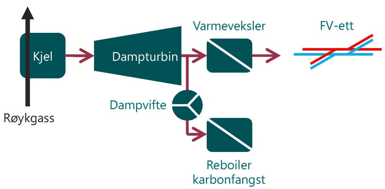
Dampvifte
An alternative is to let the steam go through the entire counter pressure turbine, and then depress it with a steam fan or compressor to the reboiler pressure, shown in Figure 17.
Conclusion on turbine alternatives
When comparing the alternatives, we see that a new counter pressure turbine comes out better than a steam fan downstream of the existing turbine. Prices are comparable. In the case of a new steam turbine, the net in 0.05 MWel is minus in electricity production. In plants where the outlet pressure is closer to reboiler pressure, steam fans are more relevant.
6.1.3 Potential operational challenges in the steam system
It is important to design for unplanned stops and other typical operating conditions. If the carbon capture supply trips, the steam demand for carbon capture will cease immediately. It will be important to detail this so that you can get rid of the steam energy in a way that does not cause too much negative impact.
Integration with existing hot water system.
Some waste incineration plants use hot water and not steam as an energy carrier. These plants do not have power generation with turbines. Since the hot water temperature in the boiler circuit is warm enough for the most common capture technologies, a partial current from the hot water circuit can be used as a heat source in the capture plant. The return circulation from the capture plant is mixed with the return circulation from the district heating exchanger(s). This way of collecting energy for the capture plant provides a 1:1 transfer of capacity from the district heating system to the capture plant.
Placing heating of the capture plant in the boiler circuit ensures a sufficiently high temperature, as most capture plants require a higher temperature, above 130 °C, than what the district heating network is on, 90 °C in the case of "KAN Referansa", as shown in Figure 18. Some catch suppliers require low enough temperatures for heat to be delivered from the carrier network.
6.2 Flue gas condensation from wet scrubber with/without heat pump
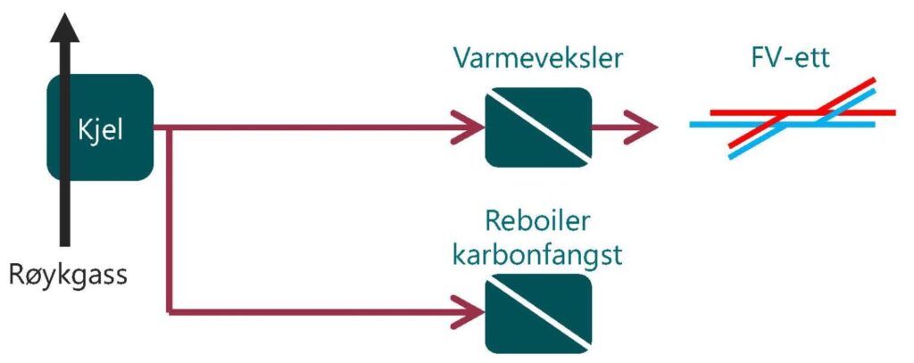
Several waste incinerators have a wet scrubber installed on the flue gas in the existing waste incinerator that cleans and cools the flue gas before it is emitted through the chimney into the atmosphere, as shown in Figure 19. This heat can be used by the waste incineration plant through a heat pump to supply to the district heating network. The heat potential available to the capture supplier and the heat demand of the capture supplier will depend on whether it is installed or not.
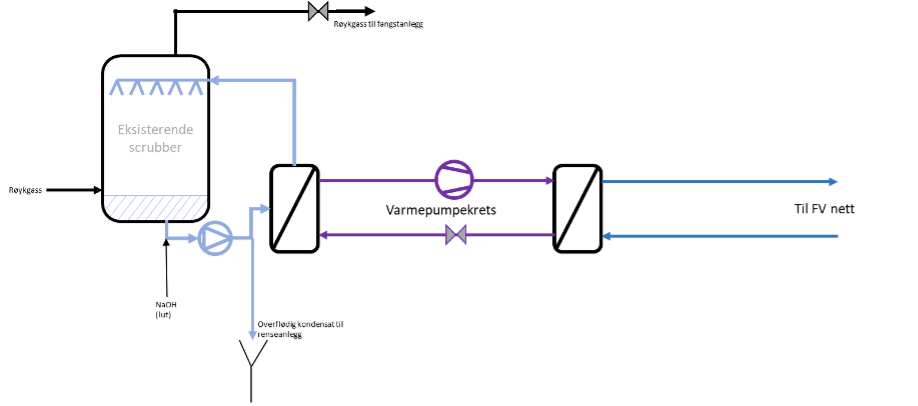
Wet scrubber will cool the flue gas below the dew point in most cases and condensate will be separated from the flue gas. This means that the liquid mass out of the scrubber is larger than onto the scrubber, and some must therefore be removed from the system. The condensate will hold sulfur and HCl and thus become highly corrosive. The scrubber water should be purified before discharge into the sewer.
The temperature of the flue gas entering the absorber tower should be at most about 55 °C, if that temperature can be achieved in existing wet gas scrubber it is best. Then you only need one scrubber, and the scrubber for the capture plant is not necessary, which lowers the complexity. This can also be combined with the heat exchange between treated and untreated flue gases.
6.3 Heating of cleaned flue gas for discharge into existing chimney
There are both advantages and disadvantages to conducting the smoke gas out of the existing chimney; The existing chimney is fully instrumented, and the flows can optionally be controlled with joint control between waste incineration and the capture plant. Since the flue gas is changed significantly after capture, a new emission permit is necessary with associated dispersion calculation to optimize temperature and pressure. On the other hand, a return to the chimney will require additional infrastructure, and coordination of cleaned flue gas and bypass flue gas can be a challenge.
The alternative is to release it from the top of the absorber tower, in many cases it will be at least as high as the existing chimney. Releasing it from the top of the absorber tower will also require full instrumentation of the flue gas (gas content, temperature, pressure, etc.), a new dispersion calculation, and a new emission permit.
To achieve a good chimney effect in the existing chimney, it is important to have a sufficiently high temperature difference between the flue gas and the surroundings. For many carbon capture plants, it will be necessary to heat the treated flue gas before it enters the chimney (or out from the top of the absorber), as the carbon capture process cools the flue gas.