Chapter 3
Recovery of waste heat from capture plants

Chapter 3
It is a project goal that steam extraction to the carbon capture plant shall not reduce the energy recovery plant's ability to supply heat to district heating when heat is needed in the DH network. Since the heat demand in the district heating network has a strong seasonal and outdoor temperature correlation, the real need to recover waste heat varies greatly.
The following principles should form the basis for prioritizing heat recovery measures:
- The lowest possible return temperature of district heating increases the potential for direct recovery and reduces the necessary temperature rise in heat pumps. The district heating company should therefore prioritize measures that can reduce the return temperature in district heating to the waste incineration needle. This also has the advantage that it potentially provides increased capacity in the district heating network.
- Direct heat exchange should be used if possible.
- Heat pumps should have as low a temperature rise as possible, which means that any heat pumps should be placed on district heating return and preheat as much as possible of the district heating circulation with the least possible temperature rise.
- Heat pumps should be designed with the flexibility to operate with varying loads. In practice, this often involves some kind of accumulation.
- The cost of installing heat pumps for recovery of waste heat should be measured against the cost of using alternative intermediate/peak load elsewhere in the district heating system. Recovery of waste heat from a CO2 capture plant with heat pumps is generally beneficial, but also entails a large investment and operating cost that cannot necessarily justify the waste incineration plant maintaining its original capacity in relation to the district heating network.
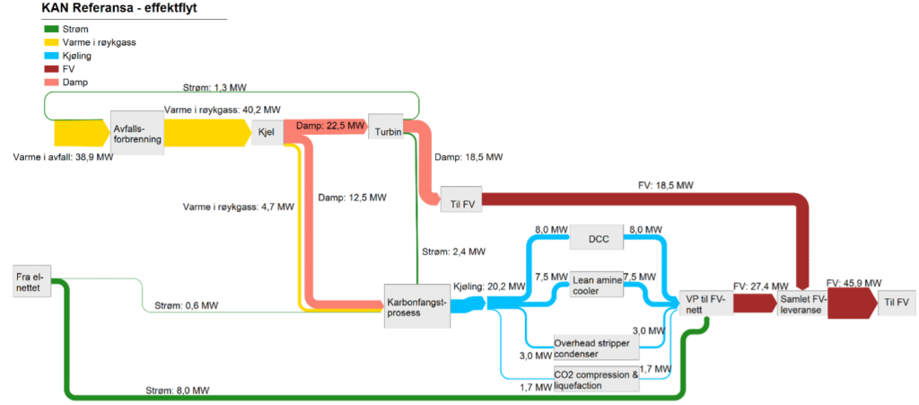
A capture plant consuming up to 12.5 MW of steam ("KAN Referansa") takes 10.25 MW from the heat supply to the district heating network, as shown in Chapter 6.1. An equivalent amount of heat, or more, should be returned to the DH network. This can be done with the help of heat pumps combined with direct heating of DH return.
There are four waste heat streams where heat can be recovered:
- Direct contact chiller (DCC) (8 MW, 55 °C / 25 °C) (scrubber)
- Lean amine cooler (7,5 MW, 55 °C / 25 °C)
- OH condenser (3 MW, heat source has 95 °C inside).
- CO2 compressor (1.7 MW, 55°C / 25°C)
Direct heat recovery from these sources may in some cases be most energy efficient due to higher temperatures but will require redesign of basic carbon capture plants.
Heat pump technology
Heat pumps can raise the temperature of waste heat through energy input in the form of heat or electricity. For industrial purposes, there are many heat pump technologies that are under development that could be relevant eventually. This means that the technologies have different maturity and different starting points, it is recommended that plant owners consider heat pump solutions from project to project. The table below provides a summary of the most common technologies with a brief assessment of their relevance to the "KAN Referansa".
| Compressor-based | Screw compressor | Relevant |
| Compressor-based | Turbo compressor | Relevant |
| Compressor-based | Piston compressor | Relevant, but often a little too little |
| Compressor-based | Rotary Vane Compressors | May be relevant on facilities with little space, but currently has a low TRL. |
| Absorption heat pump | Not relevant for KAN Referansa, but may be relevant for plants with sufficiently high vapor pressure (4-8 bar(g)) | |
| Hybrid heat pump | Is relevant to "KAN Referensa" |
Compressor-based heat pumps are largely defined by their refrigerants that condense and evaporate at different pressures. The temperatures required will have an impact on which refrigerants should be chosen, as well as reviews about the greenhouse effect of the substance, toxicity, flammability, etc. For "KAN Referansa", the following refrigerants are considered applicable: HFO r1234ZD/ZE and Ammonia in certain cases. CO2 heat pumps should be investigated where the DH network has large temperature differences.
Further analyses in this manual, it is assumed that compressor-based heat pumps with delivery to DH are based on HFO refrigerants or NH3 as refrigerant. It is presumed a Carnot efficiency is of 50-60%.
If heat pumps heat the DH return from 60°C before the DH return is sent to the WtE plant to cool the heat from the counter pressure turbine, it is important to clarify the impacts on the steam condenser downstream of the turbine with the turbine supplier.
A higher temperature of the DH water entering the steam condenser can be compensated for by the mass current in the exchanger or temperature out of the exchanger. It must be clarified to what extent this affects the power production (due to changes in the condensing pressure of the steam) and the outlet temperature of DH.
7.2 Heat pump on direct contact cooler supplying to DH
The first part of the capture plant is a scrubber called a direct contact cooler or for short DCC. DCC's purpose is to cool the gas to a temperature where CO2 absorption is most effective, as well as wash away corrosive components in the gas.
The heat available in DCC is dependent on how much heat is extracted from existing wet gas scrubs and whether it is an existing wet gas scrubber at all. For this study, an assumption has been made that there is about 8 MW available.
For "KAN Referansa" it is assumed that the flue gas must be cooled to 55 °C, this corresponds to approx. 8 MW with cooling from cooling water at 55/25 °C. A heat pump that will deliver to the DH return based on this can be expected to deliver 10.3 MW of heat at a COP of 3.9, based on η_Carnot of 57%.
This will heat the DH return of 844 m3/h from 60°C up to 71°C. The DH return of 71°C will get the rest of its heat from the boiler plant.
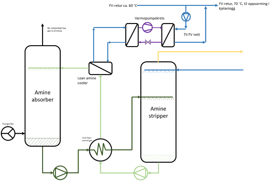
7.3 Heat pump on absorber cooling supplying to DH
In the absorber tower, an amine unsaturated with CO2 in the liquid phase is sprayed towards the flue gas, CO2 reacts with the amine and the mixture with amine and CO2 settles on the bottom of the absorber, as shown in Figure 28. Before injecting the amine, it must maintain a low temperature. The Lean amine cooler will cool amines from approx. 60 °C to 40 °C, the cooling corresponds to approx. 7.5 MW for a capture plant the size of KAN Referansa. It is cooled with water circulating between 55/25 °C. The heat available in the lean amine cooler has too low a temperature to be used directly to DH, in addition, the amount of heat is not sufficient for it to deliver the heat through a HP to the capture plant. If this heat is to be utilized, it must be utilized through HPs to the DH network.
For "KAN Referansa" it is assumed that the amine will be cooled to 40 °C from 60 °C, this corresponds to approx. 7.5 MW with cooling from cooling water at 55/25 °C. A heat pump that will deliver to the DH return based on this can be expected to deliver 9.6 MW of heat with a COP of 4 and η_Carnot of 57%.
This will heat the DH return of 844 m3/h from 60°C up to 70°C. The DH return of 70°C will get the rest of its heat from the boiler plant.
7.4 District heating direct integration with overhead stripper
Approx. 5% - 15% of the heat supplied in the stripping process through the reboiler can be recovered directly to the district heating network. A total of 3 MW of heat must be removed from the Overhead stripper condenser, of which 1.5 MW can be extracted directly to the DH. The remaining 1.5 MW must go through a HP to deliver to the DH return. The potential for taking the heat directly to DH is greatest in plants with a low return temperature of district heating. A partial stream from the district heating return is fed to a heat exchanger upstream of the main cooler after the CO2 stripper, as shown in Figure 29. Direct heat exchange takes place upstream of any heat pumps or other heat recovery. Such direct heat exchange, upstream of all other heat recovery, will always be in operation, thus permanently reducing the cooling requirement for the capture plant.
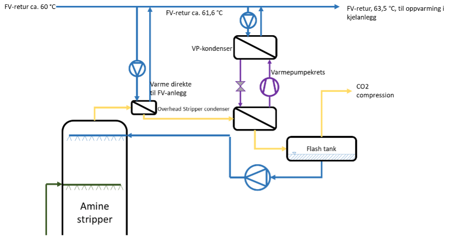
For a plant of "KAN Referansa" size with 60/90 °C return/outlet temperature, the potential for direct heat exchange will be approx. 1.5 MW, corresponding to approx. 12% of the supplied heat to the stripper. This will raise the DH return from 60°C up to 61.6°C. At the same time, the measure provides a permanent reduction in the plant's cooling requirements. In periods with very low demand in the district heating network, recovered heat will in practice only lead to increased cooling in the dry coolers of waste incineration.
If the remaining 1.5 MW is lifted to the DH return from HP, one can expect a COP of 4.8, a heat supply of 1.8 MW and η_Carnot of 59%. The heat pump will raise the heat from 61.6°C up to 63.5°C. From here, the DH return can be taken to the boilers.
For some prefabricated and modular CO2 capture plants, such heat exchange with district heating upstream of the stripper cooler will entail increased complexity and additional investments. Since the measure can be implemented passively, without increased energy costs (such as the use of heat pumps), direct heat recovery like this should be a standard solution for all facilities with available DH.
It is worth mentioning that this will be a gas/liquid heat exchanger delivered from the capture supplier, if you deliver the heat directly to the capture plant at a higher temperature, this will make the surface area of the exchanger approx. 2.3 times higher, than if cooling water of 55/25 °C is used.
7.5 Heat pump on all heat to overhead stripper that delivers to DH.
If one looks at all the waste heat available in the overhead stripper from a cooling circuit, this can only be recovered to the DH grid through a HP, as shown in Figure 30.
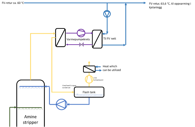
For a plant of "KAN Referansa" size with 60/90 °C return/outlet temperature on DH, the power to lift the heat to DH from HP will provide COP of 6 and a heat supply of 3.5 MW. This is based on 3 MW of heat cooling of 65/35°C and η_Carnot of 59%. This will increase the temperature of the DH return from 60°C to 63.6°C before the heat goes to the boilers.
The potential for steam production from this heat is greater than elsewhere, as the heat source maintains a higher temperature.
The potential to lift heat to steam with HP gives a COP of 2.5 and a heat delivery of 5 MW. This is based on 3 MW of heat cooling of 65/35°C and η_Carnot of 54%.
7.6 Heat recovery from CO2 compression and liquefaction
After Overhead stripping, CO2 is fed to the plant for compression and liquefaction before the gas is prepared for transport at the correct pressure and temperature, for "KAN Referansa" this will be 16 bar(a) and 20 °C. The excess heat from CO2 compression comes from cooling of CO2 between compression stages to avoid overheated CO2. This is typically higher temperatures up to 120 °C that can be used for district heating networks, the integration may need to be clarified with the capture supplier.
Parts of the heat, approx. 65%, can be extracted directly to DH or as steam to the capture plant, the remaining 35% must be cooled by seawater or similar.
For a plant the size of "KAN Referansa", it can be assumed that the power consumption for compression and liquefaction will be approx. 2 MW. The following cooling requirement will then be approx. 1.7 MW, of which 1.1 MW can be delivered directly to DH.
7.7 Heat pump on the entire cooling circuit
As an alternative to direct process integration for DCC cooling, absorber, overhead stripper or CO2 compression, one can choose to recover waste heat from the four sources' combined cooling circuit upstream of the selected cooling solution. This will then take all the heat from DCC and absorber, and part of the heat from the overhead stripper and CO2 compression elaborated in subchapters 7.2, 7.3, 7.4, 7.5, and 7.6 as shown in Figure 32.
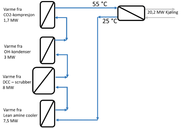
For "KAN Referansa", this corresponds to a total of 20.2 MW of cooling. It is assumed that 17.6 MW of cooling is available from a 55/25 °C cooling circuit, and 2.6 MW, from OH condenser and from CO2 compression and liquefaction, can be heat exchanged directly to the DH return.
Heating the DH return with 2.6 MW of heat increases the return from 60 °C to 62.7 °C.
Such integration with all waste heat collected in a cooling circuit has advantages/disadvantages as shown in Table 3.
| Advantages | Disadvantages |
|---|---|
| Easier integration, outside the supplier's interface. | Slightly lower temperature potential than some of the point sources since hot and cold currents are mixed and you have already been through a heat exchange between the process and the cooling system. |
| The entire recycling potential available at one point in the process. | None of the heat can be extracted directly to DH anymore. |
As shown earlier in Figure 10, "KAN Referansa" without a capture plant will deliver approx. 40 GWh/year to the power grid, this must be used as a basis for comparison to the figures that follow.
In the following sub-chapters, it is first laid as a basis that waste heat recovery should ensure to replace the DH heat lost, 10.25 MW. It is assumed that the heat pumps installed will work against the DH return, the heat that the heat pumps cannot deliver comes from the existing turbine condenser for steam. An assumption has been made that the turbine capacitor will have the same condensation pressure when the DH temperatures and quantities change. Next, it has been investigated how to increase heat delivery to DH through waste heat recovery from the capture plant. Some capture technologies will have the ability to vary the round-trip temperature of cooling water according to season.
7.7.1 Heat recovery with the entire cooling circuit of DH to maintain DH delivery.
If you want as few changes as possible in the existing heat supply to the DH grid, you can design the heat recovery to deliver 10.25 MW of heat to the DH grid. 10.25 MW of heat corresponds to the heat delivery to the DH grid as the capture plant takes from existing waste incineration plants.
If you maintain the same DH delivery in total but reduce the DH delivery from the turbine steam and deliver the heat from the HP to the DH return, the turbine condenser has slightly different conditions to work with. As shown later in Figure 33 and Figure 37, the temperature of the WtE turbine capacitor is about 70.6 °C, with continuous DH mass flow, the DH temperature output from the turbine capacitor becomes 90 °C. The turbine condenser receives only 64% of the original steam flow, it must be clarified that the turbine condenser will operate at the same pressure with a lower amount of steam.
Heat recovery to DH from the entire cooling circuit, some through HP and some directly to DH return.
The heat from OH condenser and CO2 compression is taken directly to DH and a HP is installed, which together with the direct heating will cover 10.25 MW of heat.
It is possible to extract 2.6 MW of heat from OH condenser and CO2 compression directly to the DH return. The heat pump must deliver the remaining 7.65 MW of heat. A sketch of principles is shown in Figure 33.
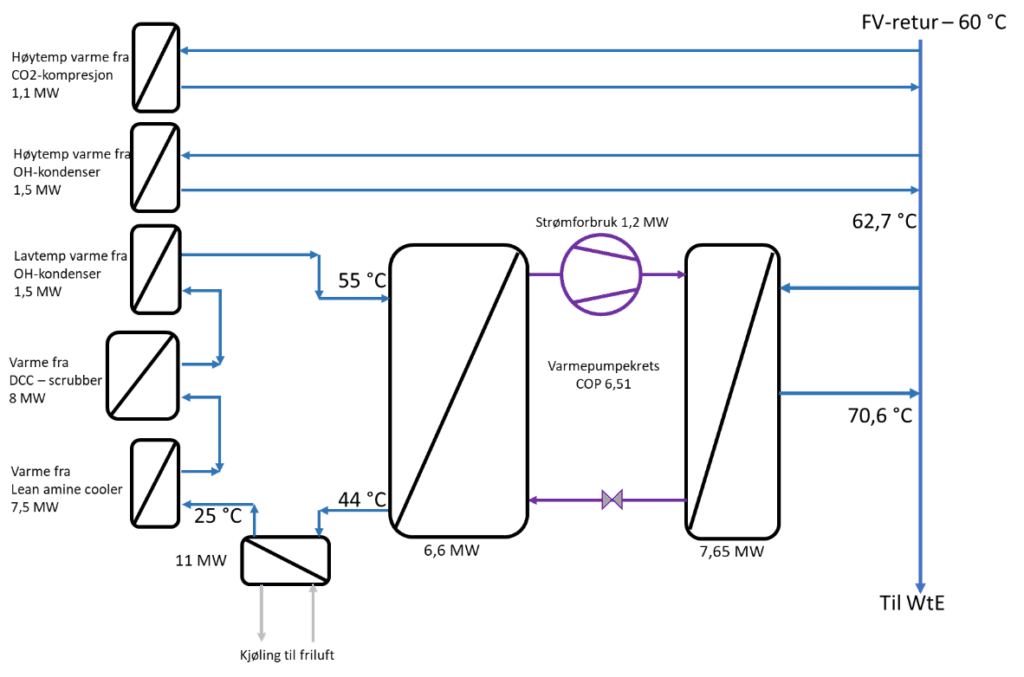
This makes for a good COP because the HP delivers to the DH return and does not have to cool the cooling water down to 25°C.
2.6 MW of heat can be collected from the capture plant directly to the DH return, heating the DH return from 60 °C to 62.7 °C.
The heat pump must cover the remaining 7.65 MW of heat, which will increase the DH return further to 70.6 °C. The capture plant needs a total of 17.6 MW of cooling (55/25 °C water), after 2.6 MW is collected directly to the DH return, the heat pump can cool the cooling water by 6.6 MW from 55 °C to 44 °C, the rest (11 MW) must be covered by external cooling.
This gives the heat pumps a COP of 6.5 which gives a power consumption of 1.2 MW and a η_Carnot of 59%. The size of such a HP would typically be a maximum of 10 x 6 x 6 m (LxWxH).
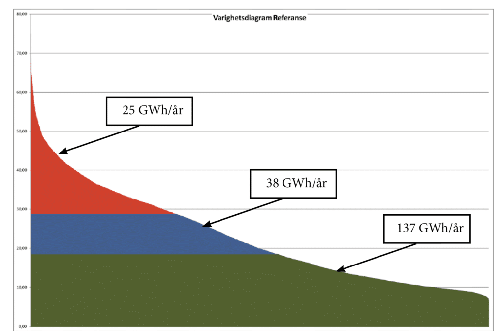
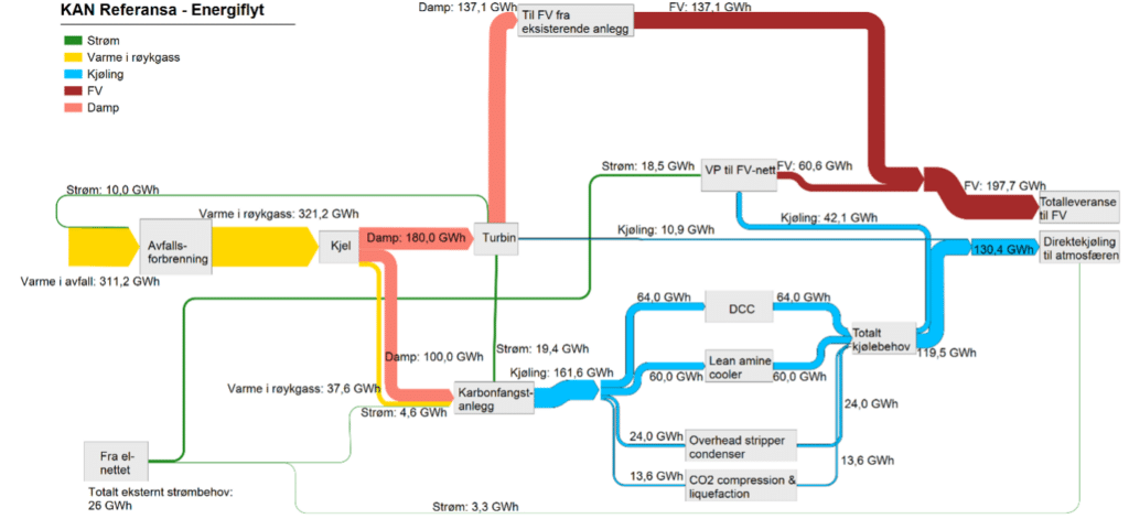
This will make little contribution to cooling the capture plant over the course of a year, it will cool about 9.2 MW of 20.2 MW of heat when the DH grid has sufficient demand. Over a year, this will correspond to approximately 38 GWh of cooling of the heat from the capture plant, out of a total of 172 GWh, shown in an energy flow diagram, Sankey, in Figure 35.
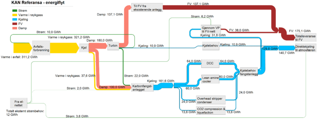
The total external electricity consumption is 10 GWh/year, net consumption goes from delivering 40 GWh/year to consuming 10 GWh/year.
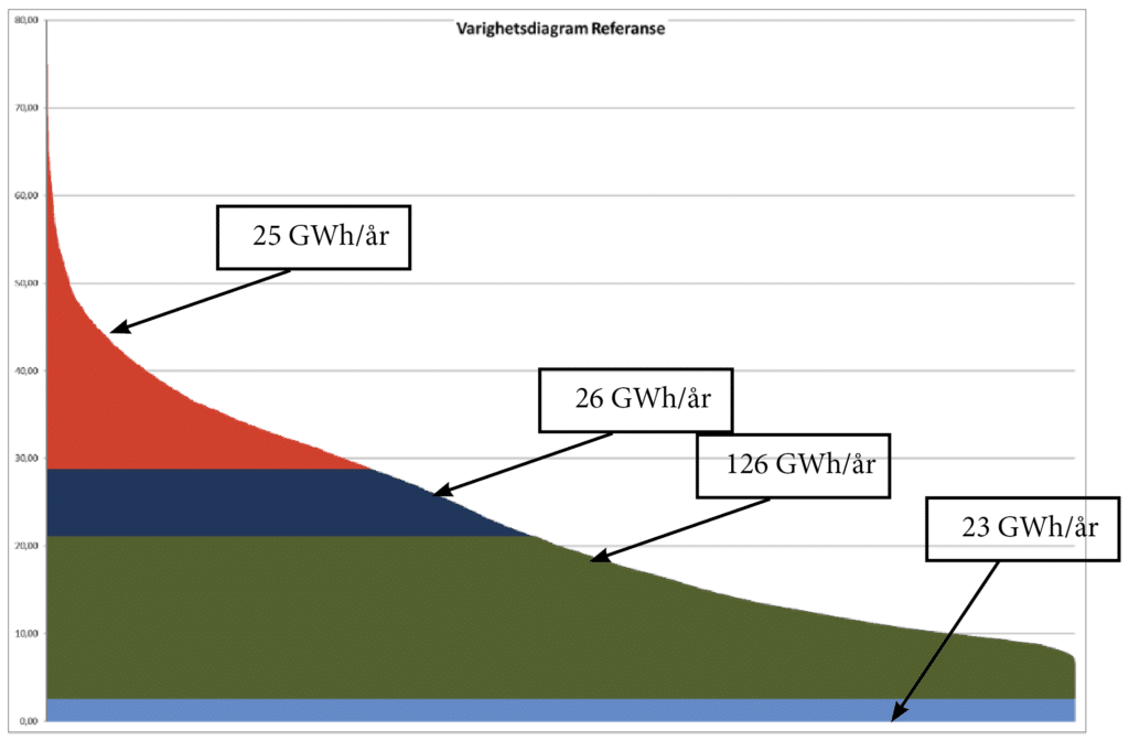
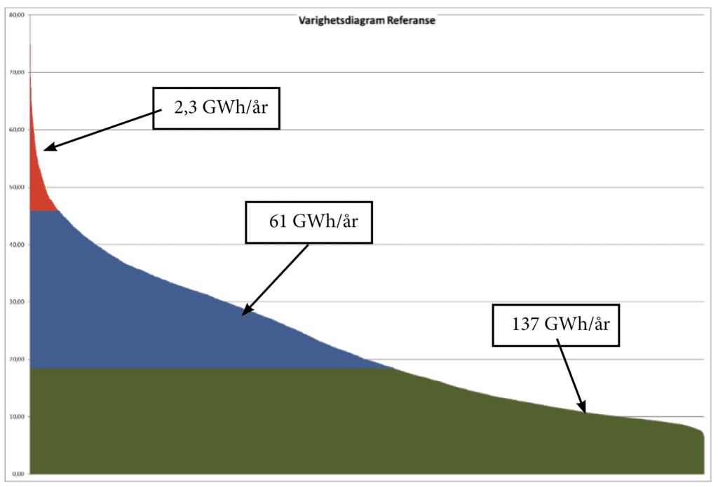
A duration diagram illustrating heat delivery to the DH grid from the various sources is shown in Figure 36. Here red is tip load, dark blue is heat delivered from the new HP at the capture plant, green is heat delivered from the existing WtE factory and light blue is heat extracted directly from the capture plant into the DH network.
Heat recovery to DH from the entire cooling circuit, only through HP.
If it is not possible to obtain heat directly from the capture plant to DH, it is likely that one will get a total cooling water circuit of 55/25 °C, to maintain the DH delivery this must go through a HP, a block diagram of the system optimized for best COP is shown in Figure 37.
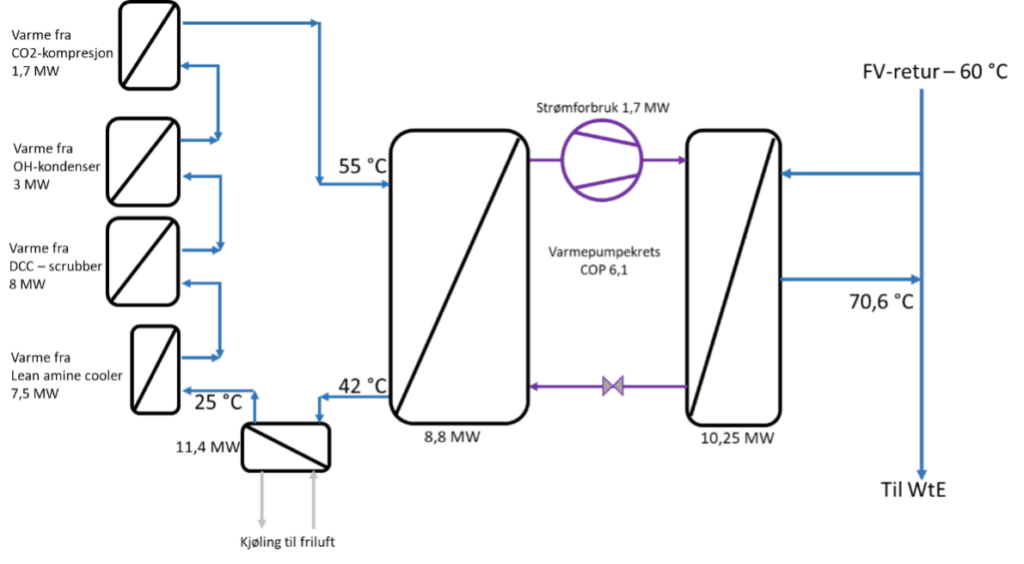
A relatively high COP is achieved due to the low-pressure rise when the heat pump does not have to take all the cooling or all the heating. The size of such a HP would typically be 10 x 6 x 6 m (LxWxH).
If you look at this over a year, you get the duration chart shown in Figure 39, which is identical to the one shown in Figure 5.
The total external electricity consumption in this case will be 12 GWh/year, therefore you lose 2 GWh/year if you cannot collect heat directly from the capture plant to the DH return. Here there are few integrations between the capture plant and the WtE factory that simplify things.
7.7.2 Heat pumps with steam delivery to capture plants.
Heat pumps can also be used to produce hot water or steam for the capture plant's own consumption. Norsk Energi has investigated this possibility through various studies.
The temperature rise in a HP that will produce steam for the capture plant will provide a lower COP than if it is used to preheat the DH return. Such integration will only be within the battery limits of the capture plant, it will have less negative impact on electricity production and district heating capacity, and less necessary integration between the incineration plant and the capture plant. This will permanently reduce the cooling requirement of the capture plant since much of the cooling takes place by the heat pumps.
The total external power consumption is relatively high, compared to the other alternatives, due to the COP of the steam producing heat pump. This alternative will pay off if the waste incineration plant has low power prices and greater challenges related to establishing cooling of waste heat.
7.7.3 Heat recovery of waste heat to DH for increased DH delivery.
If the local DH network has developed large capacity on the consumer side, but still little capacity on the production side or produces heat from fossil sources or electric boilers, it may be interesting to increase the DH delivery from the waste incineration plant through a HP. It is assumed that the amount of DH circulating is constant because there are probably limitations in pipe networks and pumps, by increasing DH delivery it is therefore assumed that one can increase the trip temperature, beyond the design temperature of 90 °C.
This will result in lower operating costs in power consumption compared to an electric boiler. The two sub-chapters that follow have investigated the potential of using the entire cooling circuit from the capture plant to heat recovery to DH through heat pumps to increase DH delivery.
Heat recovery of waste heat to DHDH for increased DH delivery without heat extracted directly from the capture plant.
If it is not possible to obtain the heat directly from the capture plant to the DH return, and one still wishes to increase the DH delivery, the block diagram will be as shown in Figure 58 and the Sankey diagram will be as shown in Figure 59.
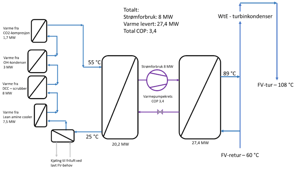
The advantage of having a HP on the entire cooling circuit from the capture plant without having any form of direct integration with the district heating network is that it provides a simpler interface with the capture supplier. The disadvantage is that the COP for the entire heat delivery is weakened, from 3.8 to 3.4.
For the "KAN Referansa" plant, a HP can take all the cooling and rise to 89°C with 8 MW of power, based on a COP of 3.4. The delivery to DH from HP will be 27.4 MW with a total COP of 3.4 (based on η_Carnot of 54%).
The WtE turbine will still deliver 18.5 MW of heat to DH as base load. The turbine condenser will have DH water at 89 °C which will condense the steam, it will increase the condensing pressure of the steam, which will reduce electricity production by 0.33 MW. The trip temperature of the DH water will be 108 °C, this is shown in Figure 59.
The duration chart for the multi-HP option that delivers to DH and increases DH delivery is shown in Figure 60. Here, green is the heat supplied from boiler plants, blue is the heat from the heat pump and red is the peak load supplied by other sources.
Duration diagram when the cooling water is collected into a cooling circuit and heated by HPs for increased DH delivery.
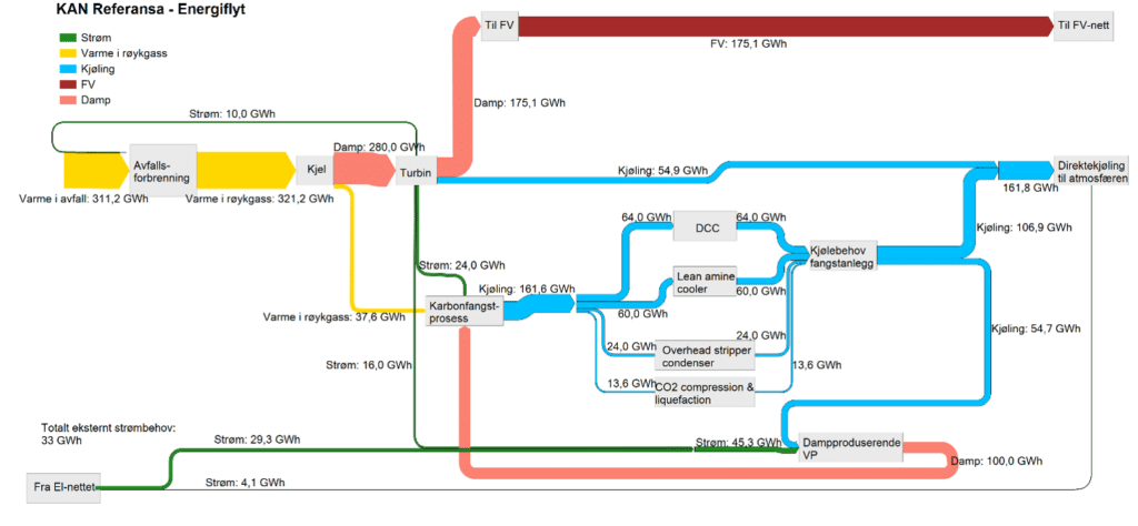
If you take this option in a Sankey diagram with energy flow over a year, you get Figure 61.

As can be seen from Figure 60 and Figure 61, one can increase DH delivery to 197.7 GWh. As shown in Figure 59, the maximum heat output of DH can be 45.9 MW, i.e. 160% of previously delivered heat output.
7.8 Summary of various alternatives for recovery of waste heat to DH and to capture plants.
There are few cases where it will be profitable to recover heat from the various point sources in the carbon capture system through a heat pump. This is because each heat source relies on cooling from 55°C to 25°C, which would give the compressor an unnecessarily high pressure rise up to the DH return of 60°C, from 25°CA good solution, however, is to collect as much heat as possible directly from the capture plant to the DH return, as this is heat that is available without any major adjustments. This should be discussed more closely with the CO2 capture plant supplier.
If you decide to heat recovery with a HP for DH, it is important to consider that the HP should have the lowest possible temperature rise, as it provides a better COP (and lower power consumption).
As seen, the highest COP is achieved by collecting as much heat as possible directly from the capture plant to the DH return and then collecting the rest of the cooling water to a cooling circuit (55/25 °C), where HP then takes the cooling from 55 °C downwards towards 40 °C and rise the DH return from 60 °C upwards. The steam taken from the turbine reduces power generation by 2.25 MW and the DH delivery by 10.25 MW, a HP to replace this DH supply needs 1-1.2 MW of power best case scenario.
Furthermore, it was shown that it rarely pays to use the waste heat from the capture plant for heat recovery through a HP back to the capture plant. This will pay off if there is great pressure to reduce the cooling capacity (MW) from the capture plant as much as possible, or if there is neither steam nor hot water available to the capture plant, and the alternative is an electric boiler. This is probably best done with an HFO-based HP.
It was shown that it is possible to increase DH delivery, so that the WtE plant can deliver approx. 197-198 of 200 GWh/year to the DH network. This can be done with heat pumps, which will be able to have a COP of approx. 2.5-3.5 to the DH network. In the best case, it can deliver 16.2 MWth more than what was done without the capture plant, with a power consumption from heat pumps of 6.9 MWel. This is relevant to consider if large parts of the DH grid are supplied by heat from fossil sources or from heat sources with a 1:1 transition from electricity to heat (electric boilers). It will depend on either being able to increase the temperature of the DH trip water or increase the amount of DH circulating from the waste incineration plant.