Chapter 3
Smart integrations
Chapter 3
The possible smart integrations between a waste incineration plant and an amine-based carbon capture plant can be categorized as shown below.
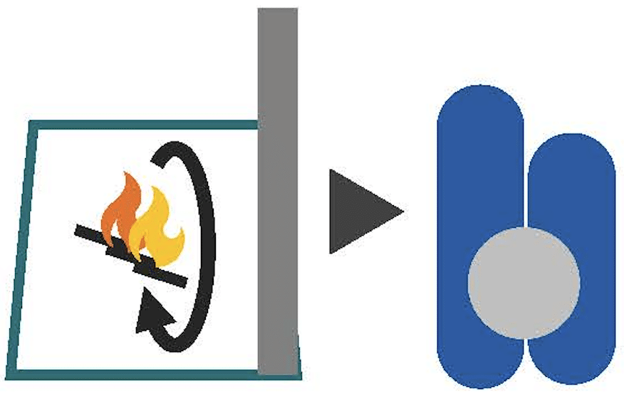
Measures in existing incineration plants
a. Increased flue gas recirculation – the use of smoke gas as combustion air for waste incineration, this will increase the CO2 concentration in the flue gas.
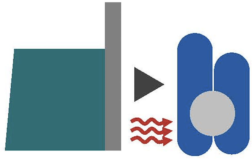
Heat supply for carbon capture (desorber/reboiler)
a. Integration with existing steam plant/hot water system
b. Flue gas condensation with/without heat pump
c. Heat exchange with purified flue gas (heating)
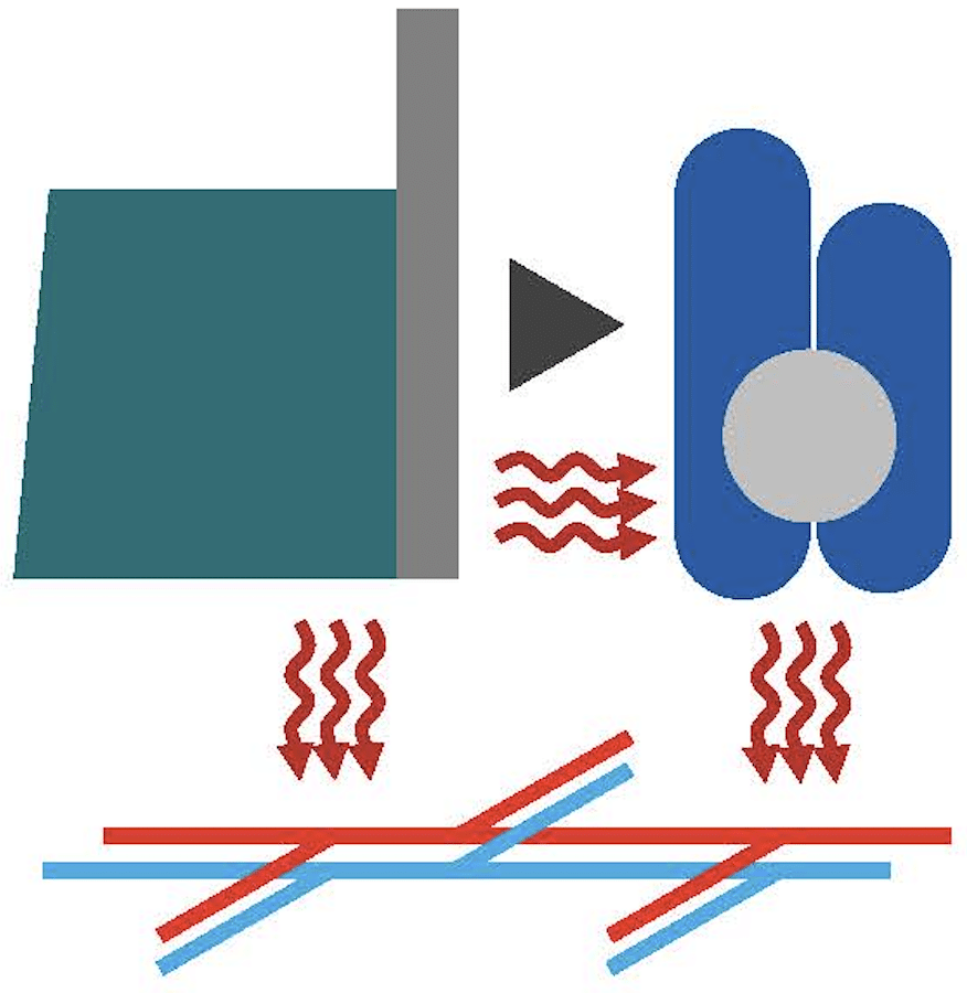
Recovery of waste heat from carbon capture plants
a. The carbon capture plant is cooled using only one circuit – the heat from here can be recovered by HP to DH or back to the capture plant.
b. Carbon capture is cooled with two circuits.
i. A circuit has a high enough temperature so that it can go directly to the DH – heat from overhead stripper condenser and CO2 compression and liquefaction.
ii. A circuit that has a lower temperature that must be lifted to DH with a HP or backed to the capture plant with a HP.
c.Heat integration at point sources in the capture plant (integration with all cooling circuits separately). This increases complexity and catch suppliers must allow or allow for this.
i. Heat pump on direct contact cooler
ii. Heat pump on absorber cooling (purified flue gas)
iii. Heat Pump on Overhead Stripper Condenser
iv. Heat pump on CO2 compression and liquefaction.